Wednesday, October 26, 2016

T3 motor G16 8v motor (T3 part 4)

I separated the transfer case, transmission, clutch and motor.

Each has "issues" and each will get it's own thread.  This is the motor post.

Issues:

-- running on three cylinders due to bad exhaust valve.

-- cracked exhaust manifold... in three places.

-- leaking seals and gaskets.

-- very dirty, oily and greasy.

these all will be addressed.  This picture shows the bad valve.
(top valve, first cylinder, from about 12:30 to 3:00 on the valve.)


This is the "good" head from T2 sitting on my "spares" shelf.


 I tacked the old head on the block and pressure washed it.  Now with the head removed again.


using  wd40 to clean the carbon and gasket residue from the block,


most of the way done, oil pan removed.


 The rear seal is out and the timing cog has been removed from the crank.  The front will be coming out tomorrow.   I might need to take the block off the stand to ensure I get the rear seal installed correctly.

-- next day --
noticed something under the timing belt cog... while the cog appeared to be positioned correctly, the keyway is damaged.


It is not as bad as some I have seen.  It at least has a SMALL notch that will keep the key in position, AS LONG AS THE COG IS FULLY ON THE CRANK.  but it would not take much to really mess up the timing.     I am thinking of a way to correct it.

update 10/28/2016 --------------------------------------------------

Ok, here is the plan:

1. Fill the space with JB Weld.

2. Grease the key and wipe of the excess.  This should act as a release agent.

3. Press it into the key way.


 4. Clean it up and hold it in place with vice grips.


5. wait 24 hours or so.


6. pry out the key.


7.  Clean it up, test fit the timing cog.


Note: while cleaning up and smoothing down the JB Weld, it cracked.  I put a few drops of super glue on the crack.

But it seems pretty good.  While I haven't tried it with the key, the cog fits over the crank.  I will replace the seal before putting it all back together.

----

-- update 11/1/16 --

after the seals were installed, (see another post on it) It took a bit of manipulation to get the key in the keyway with the cog installed.


 Blue locktite on the threads


 set to 94 ft/lbs


locked the crank with two bolts in the flywheel bolt holes and a long pry bar across the engine stand supports.

Now the day is nice, so I will be doing the stuff best done outside.... cleaning and painting.
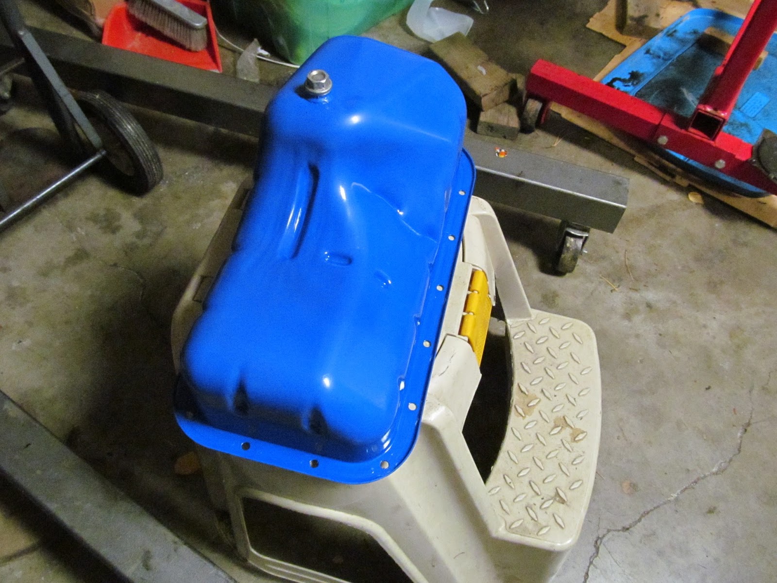


I missed taking pictures of some things. but here are pictures I have:


Head from T2 almost cleaned up enough to install.


As I did not refinish the head or the block, this seemed a good idea.


I decided I did not like the cork gasket I received, I went with the factory RTV only.


Letting it cure before the final torquing of the pan bolts.


Getting close to done.  Brand new aftermarket exhaust manifold.


Close to all I can do while on the engine stand.


T3 ECU Caps. (T3 part 3)

From all my reading I "know" the OEM Rubycon, high failure rate caps should be replaced. I opened my ECU. It looked to be original and unmolested. There were three Rubycon caps, two black and one blue.


I ordered replacement caps but kept reading.

In my reading, I came across a note that there are UPDATED Rubycon caps with an X or  K on the top.  They seem to say these Caps are fine. 


I am going to ask on the forum.

Stay tuned.

---- update 10/28/2016 ----

Advice from the forum:

"Even with updated caps, any electrolytic capacitor has a finite lifespan. As these are 20+ years old, they are due for replacement. I replace them in any new-to-me Sidekick/Tracker immediately, because I like to fix things on my terms rather than have a failure on a trail far from home. "

Thanks for the advice, I already have caps ordered, I need to practice up my soldering skills.  I haven't done PCB repairs in quite some time.... maybe 25 years?

-----------

T3 engine and drive train removal (T3 part 2)

More inspection of the drive train on T3 shows even more issues.

The front drive shaft would not rotate.  The drive train was VERY greasy so it could use new gaskets and seals.  The clutch inspection plate is missing and it is very greasy and dirty in that area.

It needs to come out to do this right.

Draining the transfer case brought up another issue... there was no lube and not only would the front drive shaft would not rotate, it would not come out either. I had to pull the drive train with the drive shaft wired up.


Missing clutch inspection plate.


Pressure washed the engine bay and the underside.


Also pressure washed the engine/transmission.


more on separate posts.

My Third Tracker (AKA "T3") Intro (part 1 of many)

I am behind on documenting my projects.

When I bought my #2 and #3 Trackers as a package deal, I was more interested in the white 1994 Tracker "T2".  The plan was to do a quick "fix" of the Black 1993 "T3" and sell it off to finance the higher quality rebuild on T2.

White Tracker on the trailer is "T2"


The black Tracker is "T3" as bought.


The more I looked at both of them, the harder T2 looks to fix properly.  I am starting with T3 while I think about how to attack T2.

While T3 ran and drove, I even drove it home but it ran very poorly.  While I have been doing little things to T3.  Changed the left front fender, left outside door handle the door panels and the grille, but I do not have pictures of these "small things."

But it pretty much sat for 6 months before I ran a compression check.  I ended up with ZERO in #1 and around 150 in #2,3,4.  (cold).  I used an inspection camera to see the top of the piston... it looked OK, but the mirror to look at the valves would not fit so I could not see the valves.

I pulled the head and found this:


Burnt exhaust valve in #1 cylinder.

Knowing it would be a while before the other Tracker needed a head,  (I was told it has a rod knock)  I did a compression check on T2.  It was good in #1,2,3 but #4 had messed up threads for the spark plug... I could not get a good reading.  Figuring it was good enough, I pulled the head, cleaned it up and fixed the threads in the spark plug holes.


Almost ready for use.  It still needs a new front seal and O-rings for the distributor.


Wednesday, August 3, 2016

A few pictures for the TracKick forum

Pictures for the TracKick forum.  Seems I accidentally deleted a few pictures.

--- resetting airbag warning light ---

For more information on your specific vehicle, please visit the website : codes.rennacs.com


---- temp warning system ----


---- OBD2 bluetooth scanner ----


----------- Roof Rack ----------------------
My 1992 when I bought it had a roof rack


I did not need it and it made quite a bit of wind noise.


The six feet were not very strong


Each foot was screwed to the pinch weld with one or two screws.  I know there wasn't more than ten  little screws.

another pic for the forum, this is a valve cover on a Suzuki Swift.  I would like to know if it will work on a G16 8v motor.


here is the current cover. (head and intake removed from the motor.)


----------- 11/1/2018 added info:

Here is a picture of when I added a IAT sensor to my 1992 Sidekick to make the 1994 ECU happy.   The red arrow at the bottom is where I drilled a hole in the air filter case for the probe.  The green arrow points to the green speaker wire routed to the ECU.  (I need to find the pin numbers)  If I did this again, I would be sure and follow the same harness as the other wires going to the ECU... just in case I needed to pull the harness in the future.


I haven't found the pictures for CODE 51 due to not having a EGR temp probe (EGRT), But from a post on the forum in 2013 and it from memory:

"My 1992 four door Sidekick came to me with a computer labelled: 33920-58B00. Near as I figure it should have been a 33920-58B40. (That is what I had been looking for.)

Nether the engine that was in the car, (not original) or the JDM motor I replaced it with had a EGR temp probe (EGRT), but had the wiring. (The plug is on top the motor near the rear.... right above the EGR valve.)

After I had installed the JDM motor, with its WORKING EGR valve, I could reset the code 51, but it would return after about 5 minutes of DRIVING. It didn't seem to "pop" when just idling.

I found a chart in the FSM with the testing values for the EGRT, and picked a resistance value from the middle of the chart In a local electronics store I picked up a pack of resisters close to that middle value.  Bending the leads on the resistor, I stuck it directly into the empty EGRT plug, taped it up and no more code 51!

I stopped looking for a new computer."

I haven't been able to find what I used, but looking at FSM Figure C1-23 - REGTS Characteristic, I would select a 100K ohm resister. But it looks like anything from 125K to about 40K should work.

EGR -------------------------


parts shelf


Auto Trans check from Sidekick FSM


Saturday, July 16, 2016

Horn wiring diagram

this is for someone on the TracKick forum http://www.suzuki-forums.com/suzuki-sidekick-escudo-vitara-geo-x/


Horn wiring diagram from the 94/95 wiring manual.