Saturday, November 26, 2016

T3 timing marks, G16 8v (T3 part 8)

 ---------------------------------------- timing marks

This is the "best" picture I have of a cam timing belt sprocket.  Note the two marks.  60A (in the yellow section) is the one for G16 motors.  Then about 4:30 is an "80C".  I have been told this is for a twin cam motor.  But you can see how it can be improperly installed, making the "80C" the "correct" mark.


Why the odd colors?  I do not have a picture of the completed paint job, but it now has yellow and black at the #4 position and a blue/white at the #1 position. I painted the sprocket so I could check the timing with the cover still on.  Here it is sitting at TDC #1 ready to fire.  (Positioned to install the distributor.)


This next picture is one of several reasons why:


If you look closely you will notice the small notch for TDC is no longer lined up with the key-way slot on the crank.  The outer ring has shifted a few degrees from the center, making the timing mark inaccurate.  This is the only Suzuki harmonic balancer I have seen that has shifted.  I have seen some older, 70's GM balancers almost 180 degrees out!

Wednesday, November 2, 2016

T3 motor seals, G16 8v (T3 part 7)

This motor and transmission were covered in oil and grime.  As this motor was out and stripped down to the short block, I could not see NOT changing the seals.

As the subject of seals often comes up in the forum, I separated it from the engine post.

This is the method I used:

Drill or otherwise poke a hole in the seal.   I have hammered a nail into seals in the past.


Pry out the seal attempting to keep from damaging the surrounding area.


Clean (shown vacuuming) any bits and pieces from the old seal  (drilling makes some) and ensure the mating surface is ready for the new seal.


Collect the tools needed to install the seals.  I just pulled out the tool kit I collected when the dealers closed.  ( I bought several incomplete sets off eBay to make one complete set.)


This is an incomplete set but it has the tools for this job.   The manual is invaluable to select the proper tool.


The blue cone is the rear main seal tool, The block cone and bolt are for both front seals the small black sleeve is to protect the seal during the front crank seal install.


 A trick from the low range off road instructional videos,  wet the seal by dropping in water.


Place it in line with the hole, and drive it in with the tool.  With the water "lubing" the edge of the seal, I really did not need the mallet.  But I still smacked it a few times.


 Most seals are properly installed when the edge is flush with the surrounding area.

You do not NEED the proper tool to install seals but they help to set the seal at the correct depth without over driving the seal to deep and possibly beyond the point it can keep the case sealed.  (Both the heads I am working with on this project had seals driven too deep.)  People normally use a appropriate sized socket or pipe to drive the seal into place.  (I have even installed the larger rear seal on a J18 motor with a couple of PVC pipes and a block of wood.)  Seal installation without the proper tools, using the "water trick", it should be fairly easy to do and ... to over do.  Be careful as you drive the seals in.

This is a rear seal driven in to the proper depth.


Lube the rotating part with some type of lube.  I used grease.


It wasn't hard to slip the seal over the end of the greased crank and bolt the seal carrier in place.   OBTW: The old seal was very brittle and hard, but it was in one piece.


 Below I am greasing the sleeve and the crank for the front seal install.  If you do not have a sleeve, there is a trick of making a sleeve out of slick plastic electrical tape.  You wrap the crank snout with tape so it kind of looks like the sleeve in the picture below.  Grease it up and continue.  I have installed them in the past with tape, grease and a socket. 


Soaking the seal.

 Place the seal and install the tool...


 Tighten down and the seal is in place.  The tool keeps the seal from being "over driven."


Perfect!


 I followed the same procedure for the cam seal.  No sleeve needed.
  

OBTW the exact same seal is used for both the front crank and the cam.  Both front and cam seals were fairly new and really did not need changed.... other than the cam seal have been set too deep.
Yes, you can do this without the fancy tools, but the water trick and the proper tools make it simple.

Now back to the engine post....

BE SURE TO TORQUE THE LARGE CRANK BOLT TO THE PROPER SPECS.... IT IS 94 ft/lbs for the G16 motors.  Too low of torque has been known to lead to damaged crank key-ways. 


Friday, October 28, 2016

T3 Body Metal Issues (T3 part 6)

There are a few problems with the body on this 1993 2 door TinTop Tracker.

Besides the "normal" dents and stuff (no real rust)

1.  Somehow the hood came unlatched and damaged the hood, the windshield and  the area around the passenger side wiper pivot and both wipers.

2. The driver's door was over extended, damaging the fender (swapped out with a used one already) and ripped the door stop mount from the door sill.

When I pulled the head, I noticed I had much better access to the cowl area.  So figured it would be a good time to fix the wipers.

Before


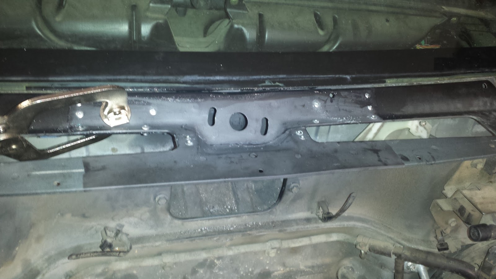
Wiper linkage/assembly removed.


Trying to find "good" metal, found cracks in the metal  quite a way from the mounting point.  Cutting out the bad section.


 I cut a larger part from the damaged body of my parts car.  Test fitting.


Treat and prime the area.  I am a poor welder at best, so I am going to go with structural adhesive and pop rivets.  Looks are not that big of a deal as it is covered by the plastic cowling anyway.


This is a test fit after priming with the wiper system installed.


The adhesive I used was left over from a motohome panel repair.  Most of the tube had hardened so I had to poke a hole in the side to get usable adhesive.  I already tossed the leftovers, so no pictures.

The adhesive (3M) is a permanent bond with a little bit of flex, and it is used in aircraft, aerospace and marine construction and repair.  They say it is paint-able and actually holds the paint.   (Unlike other paint-able adhesives/sealers.)  But being black on a black car... not an issue.

Here it is after pop-riveting into place.


The rivets are more to hold it in place during cure... it took several days to fully set up.

This is pretty much done until I get T3 farther back together.

-------------------------

Now for the door stop mount.

The problem:


I noticed this in my scrap pile.  It came from a pop-up canopy that have been getting popular lately.  This was from one just a step or so above the cheapest quality.  The hole is in the right place, the tube is the right size and shape.  The gauge is a little lighter than I would like.


I ground down the plastic end cap and drove the solid plug into the tube thinking it would provide support when clamping during my manipulation.

Some work with a grinder made the correct shape and the slot needed for the linkage to the door.

I drilled a hole to be a crack stop as I split the tube.


 Carefully sawing split the tube.


Unfortunity, the metal cracked as it was split.  I do not think this metal will do the job as needed.
But I will finish it (some) to see if I get ideas for the real repair. 


Both legs pread 


Slipping it into the body.


Set in place.  I would put something in the slot to wedge onto holding it in place while  drilling and pop riveting.  To bad the metal is so brittle.


Ideas?  Heat?  something from home depot (brackets/conduit tube) ??

--- thinking now, while I work on something else. --

--- update 11/1/16 ----

Stopped by home depot and found some interesting little straps.


clamped them to a scrap computer case and heated the metal.


 a few taps with a hammer and I have something to try.


 A quick test shows these MIGHT have a little too much protrusion from the door sill.  It might keep the door from closing.  Maybe it would not be a bad thing to do some actual measurements ?? !

---
11/10/2016  (Marine Corps Birthday!) Update

Yes, I trimmed back the brackets a little and hit the exposed sections with primer.

I had planned on using pop-rivets, but I couldn't find any large enough.  Looking in the hardware store I found some 5mm U nuts. 


I drilled some holes into the door jam and positioned the plate.  Note the wire attached to the plate.  I had dropped it before and it took me about 4 hours work spread over several days to get back out!


After getting both plates installed and bolted down.  If I had known I was using U nuts rather than pop rivets, I would have left the bracket longer...


... as now it is almost to short!  The original hole was better also.

But the important thing is.... It is done!


Thursday, October 27, 2016

T3 5 speed transmission and transfer case (T3 part 5)

T3 5 speed transmission and transfer case (T3 part 5)

I drove this thing home.  I even test drove it before I bought it.  I THOUGHT the 4x4 worked, but I really did not do much in the time I had.

Anyway the transfer case has a problem with the front output.  The driveshaft is stuck in it and it will not rotate.  Putting it in any 4x4 position, has no effect.

I suspect the chain is toast and this whole thing needs redone.

Separating the T-Case from the transmission, I found a quart or so of lube in the space between them.  That should be a dry space.

Here is what was in there:


The missing seal was loose in the same space.  Both seals had been held it by RTV.  The lube had a strong sulfur odor... something I associate with "non-yellow metal safe" GL5 lube, that should NOT be used in either the T case or Transmissions.  While it is good for the gear design in the differentials, it is bad for the brass parts found in the center of the car.  (Use GL4 only there.)

Something tells be that this transmission has been "rebuilt" and now needs gone into ... again .... just to see if everything is OK.

Looking on my "spare" shelf I see this transmission:
 

It is a JDM 1998 5 speed transmission I bought a while back for a project that went another direction.  From what I understand, the only difference are the output splines on the transfer case.  If I could find the correct drive shafts, it would work.... but that is also one of the reasons that project changed directions.

Hold on...   Right next to it, is the 3 speed auto with T case, that came with a 1989 basket case project.  Looks like it will fit.  Drive shaft splines are the same as the 1993.

Here it is separated from the transmission:


Next step here is to clean it up and inspect both this T case and the '98 trans.

Wednesday, October 26, 2016

T3 motor G16 8v motor (T3 part 4)

I separated the transfer case, transmission, clutch and motor.

Each has "issues" and each will get it's own thread.  This is the motor post.

Issues:

-- running on three cylinders due to bad exhaust valve.

-- cracked exhaust manifold... in three places.

-- leaking seals and gaskets.

-- very dirty, oily and greasy.

these all will be addressed.  This picture shows the bad valve.
(top valve, first cylinder, from about 12:30 to 3:00 on the valve.)


This is the "good" head from T2 sitting on my "spares" shelf.


 I tacked the old head on the block and pressure washed it.  Now with the head removed again.


using  wd40 to clean the carbon and gasket residue from the block,


most of the way done, oil pan removed.


 The rear seal is out and the timing cog has been removed from the crank.  The front will be coming out tomorrow.   I might need to take the block off the stand to ensure I get the rear seal installed correctly.

-- next day --
noticed something under the timing belt cog... while the cog appeared to be positioned correctly, the keyway is damaged.


It is not as bad as some I have seen.  It at least has a SMALL notch that will keep the key in position, AS LONG AS THE COG IS FULLY ON THE CRANK.  but it would not take much to really mess up the timing.     I am thinking of a way to correct it.

update 10/28/2016 --------------------------------------------------

Ok, here is the plan:

1. Fill the space with JB Weld.

2. Grease the key and wipe of the excess.  This should act as a release agent.

3. Press it into the key way.


 4. Clean it up and hold it in place with vice grips.


5. wait 24 hours or so.


6. pry out the key.


7.  Clean it up, test fit the timing cog.


Note: while cleaning up and smoothing down the JB Weld, it cracked.  I put a few drops of super glue on the crack.

But it seems pretty good.  While I haven't tried it with the key, the cog fits over the crank.  I will replace the seal before putting it all back together.

----

-- update 11/1/16 --

after the seals were installed, (see another post on it) It took a bit of manipulation to get the key in the keyway with the cog installed.


 Blue locktite on the threads


 set to 94 ft/lbs


locked the crank with two bolts in the flywheel bolt holes and a long pry bar across the engine stand supports.

Now the day is nice, so I will be doing the stuff best done outside.... cleaning and painting.


I missed taking pictures of some things. but here are pictures I have:


Head from T2 almost cleaned up enough to install.


As I did not refinish the head or the block, this seemed a good idea.


I decided I did not like the cork gasket I received, I went with the factory RTV only.


Letting it cure before the final torquing of the pan bolts.


Getting close to done.  Brand new aftermarket exhaust manifold.


Close to all I can do while on the engine stand.