Friday, November 28, 2014

Stripping the parts car (Part 4, The Dash)

To get the main harness out of the car, it is easier if you remove the dash.  It is also a good possibility that I'll be using the 1994 dash harness behind my 1989 JLX style dash. In any case, I'll need to compare connectors and pins.  The '94 really doesn't need it anyway...

So...
The steering wheel and the covers for the column need to be removed.  I am fairly sure you can leave the speedometer cluster installed in the dash.  Just disconnect the cable.  You should be able to reach it after the dash is unbolted.
 

You can see the (removed) covers for the top three screws.  There are also three screws at the bottom lip in each foot well. 

I keep forgetting about the grab bar on the dash.  It bolts (4 bolts) to these brackets.  (Shown after dash removal.) They are reached after removing the glove box.


I pulled it out a little and checked that all had been disconnected.  There are 4 or 5 connectors on the drivers side and a few on the passenger side.  The exact number will vary with equipment installed.  Power door locks, power windows,  mirrors and the like.

After making sure all was disconnected, I slid the dash back and rotated it down.


Here is the "stuff" behind the dash... including the main harness.


There are a few wires that hadn't been disconnected. They wires that did not disconnect are from the Suzuki alarm system  I removed this alarm and stored it... most likely never to be used again.  (much better system available for cheap now days.

EDIT: adding picture to show location of the "warning control buzzer."  Note that this is a 1994 8v model.  I have seen this sam buzzer in 3 different locations.


If the dash was installed, this would be above and just to the right (towards the door) of the glovebox.  Notice the bolts/bracket for the grab bar?

Stripping the parts car (Part 3, 8v engine harness)

Now with the body on something stable:


Time to work on the wire harness.  My '89 doesn't have a main or engine harness.


The engine harness

 The end at the fire wall


Just inside the fire wall is the plug to disconnect the engine harness.  I should have left it connected to the engine!


Thursday, November 27, 2014

Stripping the parts car (part 2, still chassis)

The body made it "safely" to the supports.  Now it is safe to strip the parts for use on my '89 tin top.


 Used the old "rattle" cans of black paint on the chassis.

I later pulled the motor and transmission and put it in th garage until the tin top body is ready.


 This picture was requested by a "TracKick" forum member.  It is the throttle and kick down cables on the rear (firewall end) of the throttle body.


Stripping the parts car (part 1, Separating the body and chassis) 1994 Sidekick, 1.6 8 valve, two wheel drive.


I have pulled the chassis from my parts Sidekick.  I'll need to figure out a better method of lifting the body from the chassis as I only dropped the body twice when lowering it. :(


I was hoping the cherry picker could reach all the way to the body balance point.


Even with the load leveler all the way forward, it was not the balance point.


I needed to use my motorhome jack to lift the front.


Supported for the roll-out.


 Chassis out, now to lower the body to supports (old tires).


The motorhome jack slipped and the nose hit the ground.  

The seam for the fender (with the bolts) landed on the jack stand.


Doesn't look very safe from this angle.

Tuesday, September 16, 2014

Sidekick Sport J18 engine install

I noticed I didn't say anything about my Sidekick Sport after buying it.

I had it on the road after changing the front tie rods and rims.  They were damaged when I bought it, totaled from CoPart auto auctions.

I also set it up as a towd and have towed it to California/Arizona and back a couple of times.  (I did burn up a front hub in Arizona, on our way to Oklahoma, and had to leave it at my brother's house.  We fixed it on the return trip.

It works well, but is a little too heavy to pull with my GMC. 

BUT.... We found out why the Suzuki "J" motors are sensitive to oil.  Both being full and being clean.

This is the motor after pulling and disassembly:


Notice the hole in the side of the block... there is a matching hole on the other side!  The number one connecting rod blew... taking out the oil pump and both sides of the block.

I called Foreign Engines http://foreignengines.com/ from the northwest US. They delivered a J18 (front wheel drive application) to my door in under 24 hours.


It took almost a year, but I got it installed:


That seemed to be my last picture of this project.  I THOUGHT I had taken some during the actual install.

I went out and took a few today:


Sharp eyed readers will notice the exhaust manifold isn't a J18 item.  My J18 one was cracked... just a little. ;) I got a manifold from a J20 equipped Tracker... I think a 2000.  But I needed to find a way to connect it as the newer applications use the cat as the down-pipe and can not get them from Pick-n-pull.  I had a muffler shop connect it up along with a larger pipe and muffler.


It is a bit loader than I like but WELL within legal limits.

Here it is today, not bad for something that has about to be scrapped more than a few times!


Now I need to get back to work on my current project:


UPDATE to this page:

I was asked to provide pictures of my rear seal installation tools / method.  I destroyed several seals trying different methods until I hit on this one.


Plumbing parts from home depot.  take the seal with you and pick out the size you need.


Three studs from exhaust manifold to head connection. to hold the guide in place.


there was an angled lip on my "guide" pipe.  I was concerned it would catch, but it seemed to work fine with it.


Use grease to ensure the seal slides easily.


 The seal installation tool... I put a block of wood across the open end and hit it with a mallet.  I can not remember what the duct tape was for... depth indicator?


 Went in first time with no problems. Just remove the studs and you are good to go!


Installed seal.


Sunday, September 14, 2014

Sidekick body swap

On to the next project.

I have been collecting parts for this build for a while.

I want a 2 door Tin Top Suzuki Sidekick automatic to tow behind my motorhome.  While I do not NEED 4 wheel drive, I do need the transfer case to serve as a drive line disconnect.

I found a body on criagslist: 

I bought it and had it delivered.

I later found this one:


I bought it and also had it delivered.

It has been a while... over a year, so it is time to get started.

Pulling the frame complete with engine and running gear from the blue 1994 Sidekick, and installing the transfercase from the red 1989 tin top. them slipping it all under the TinTop body.

Oh ya, I need to transfer the front inner sheet metal, as the TinTop has the right front corner missing.


So, I need to start.... 


Tuesday, August 26, 2014


I have installed, tested and finally got the CC working in my  4 door, 16v, 4 speed auto, 1992 Sidekick.  This car did not come with any wiring for a stock CC unit.

During preliminary testing, I had already tapped into the signals for VSS and brake lights at the transmission computer connector. All I needed was power (tapped into the cigarette lighter) and ground. (Used a handy screw that contacted the metal structure under the dash.)   All the other connections were in the harness I made up connecting the CC unit to the remote.

CC unit Electrical Connections:
A ........ Cruise "ON/OFF" input
B ........ Set/Coast input
C ........ Resume/Accel input
D ........ Brake/Clutch normally closed (12v) input
E ........ Ground
F ........ Switched +12v
G ........ Brake/Clutch normally open (0v) input
H ........ Cruise inhibit signal
J ........ Cruise engaged signal
K ........ VSS signal

Pins A and F plus power for the remote came from the cigarette lighter through a toggle switch on the dash.  This switch is more of "positive shut off" safety item and really could be left on all the time.  In fact the cc is always powered in most applications and needs to see the brake being applied a few times before the cc will engage.  This same power is also routed to the "common" contact of the relays A, B and C on the remote.  (relay D is unused.)

Pin B is connected to the normally open (NO) contacts of the relay "B" in the remote unit.  To set the cc, or slow down, press the "B" button on the remote.

Pin C is connected to the normally open (NO) contacts of the relay "A" in the remote unit.  To resume cruise, or accelerate, press the "A" button on the
remote.

Pin D is connected to the normally closed (NC) contacts of the relay "C" in the remote unit.  To disengage (coast), press the "C" button on the remote.

Pin E, ground, is connected to the other items needing ground and then connected to a grounded screw under the dash.

Pin G is connected to the brake lights.  I tapped this wire at the transmission computer.  (Green wire)

Pin H, Cruise inhibit signal, is left unconnected with this CC unit.  I have read that there are units that require a digital signal before the cc will engage (mostly in later model car CC units.... just before the CC was integrated into the PCU.) All of the units I have tested work by leaving disconnected or grounded.  My tester has open, 12v and ground capabilities for this line.

Pin J, Cruise engaged signal, is also left unconnected.  I understand there is a CC light in the TracKick cluster but haven't researched/tested if I can make it work with a GM CC unit.  i suspect so...

Pin K is connected to the vehicle speed sensor (VSS) from the speedometer cluster.  I tapped this wire at the transmission computer.  (yellow wire)


The last picture shows the jumper on the remote unit that needed to be removed to make the remote work as momentary switches.  As delivered, it worked as one press on, one press off.... not what i needed!

I clamped the CC cable to the dash structure just inboard of the gas petal.  I connected it to the petal with zip ties.  (Come on, this _IS_ just a test of concept!)


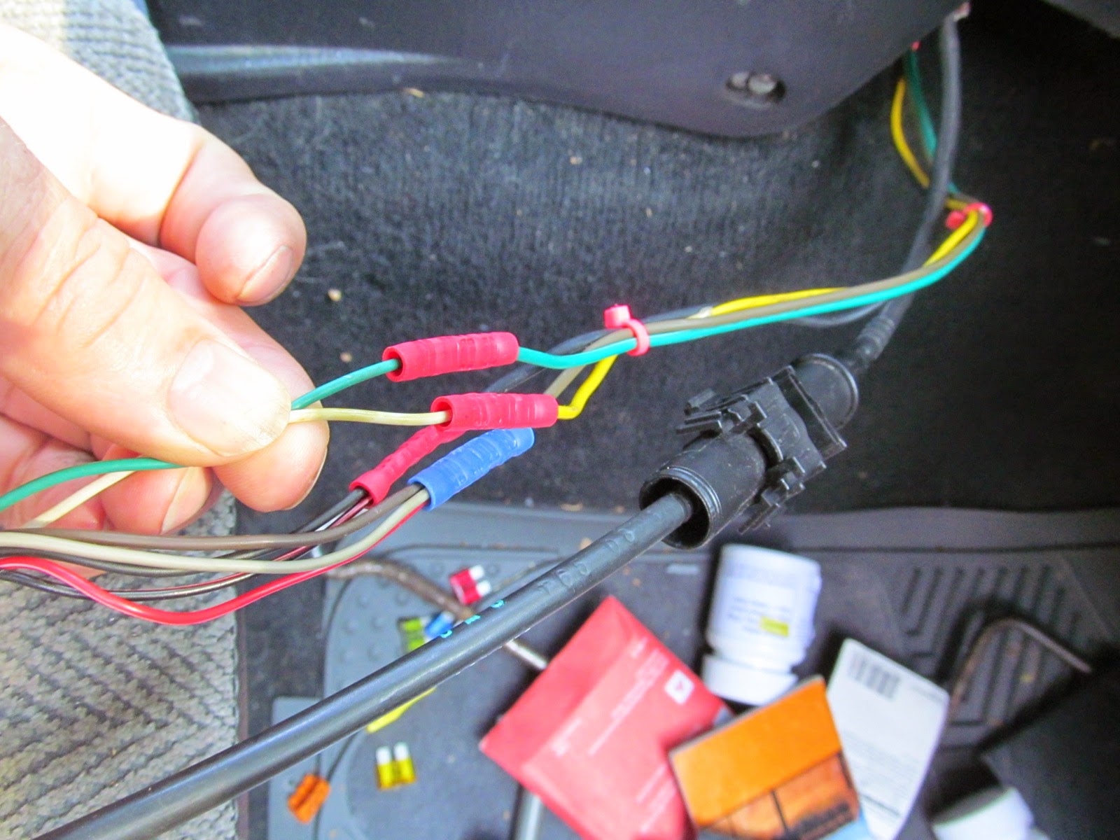
You can also see the scotch locks I used to tap the wires at the transmission computer.  Sharp eyed readers might notice the wire color swap at the connectors above the cable clamp.  I had made a mistake when making my "harness" and connected a green wire on the CC pigtail from Pin K to a green wire I had expected to connect to the brake lights.  (Green in the TracKick harness)  It should have been to the yellow wire, to match the yellow VSS wire in the Sidekick....


Oh well... I do not think anyone else will be working on it anyway.

After getting the CC to work, I moved the CC unit under the driver's seat and strapped it to the jack handle.


I still haven't taped the remote to the steering wheel, but as my sone is currently driving this "Kick" it isn't a problem.  He doesn't like to use cruse and isn't driving very far anyway... just 5 miles to work.