Tuesday, August 26, 2014
I have installed, tested and finally got the CC working in my 4 door, 16v, 4 speed auto, 1992 Sidekick. This car did not come with any wiring for a stock CC unit.
During preliminary testing, I had already tapped into the signals for VSS and brake lights at the transmission computer connector. All I needed was power (tapped into the cigarette lighter) and ground. (Used a handy screw that contacted the metal structure under the dash.) All the other connections were in the harness I made up connecting the CC unit to the remote.
CC unit Electrical Connections:
A ........ Cruise "ON/OFF" input
B ........ Set/Coast input
C ........ Resume/Accel input
D ........ Brake/Clutch normally closed (12v) input
E ........ Ground
F ........ Switched +12v
G ........ Brake/Clutch normally open (0v) input
H ........ Cruise inhibit signal
J ........ Cruise engaged signal
K ........ VSS signal
Pins A and F plus power for the remote came from the cigarette lighter through a toggle switch on the dash. This switch is more of "positive shut off" safety item and really could be left on all the time. In fact the cc is always powered in most applications and needs to see the brake being applied a few times before the cc will engage. This same power is also routed to the "common" contact of the relays A, B and C on the remote. (relay D is unused.)
Pin B is connected to the normally open (NO) contacts of the relay "B" in the remote unit. To set the cc, or slow down, press the "B" button on the remote.
Pin C is connected to the normally open (NO) contacts of the relay "A" in the remote unit. To resume cruise, or accelerate, press the "A" button on the
remote.
Pin D is connected to the normally closed (NC) contacts of the relay "C" in the remote unit. To disengage (coast), press the "C" button on the remote.
Pin E, ground, is connected to the other items needing ground and then connected to a grounded screw under the dash.
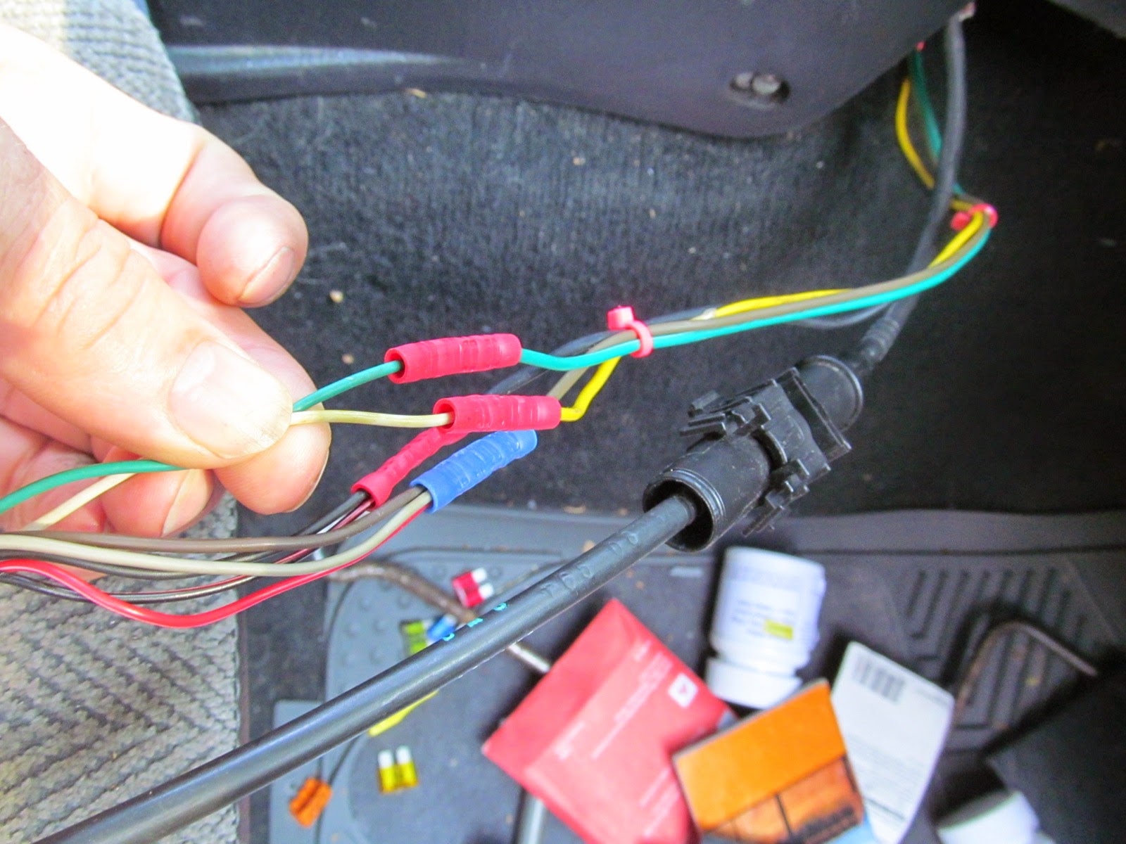
Pin G is connected to the brake lights. I tapped this wire at the transmission computer. (Green wire)
Pin H, Cruise inhibit signal, is left unconnected with this CC unit. I have read that there are units that require a digital signal before the cc will engage (mostly in later model car CC units.... just before the CC was integrated into the PCU.) All of the units I have tested work by leaving disconnected or grounded. My tester has open, 12v and ground capabilities for this line.
Pin J, Cruise engaged signal, is also left unconnected. I understand there is a CC light in the TracKick cluster but haven't researched/tested if I can make it work with a GM CC unit. i suspect so...
Pin K is connected to the vehicle speed sensor (VSS) from the speedometer cluster. I tapped this wire at the transmission computer. (yellow wire)
The last picture shows the jumper on the remote unit that needed to be removed to make the remote work as momentary switches. As delivered, it worked as one press on, one press off.... not what i needed!
I clamped the CC cable to the dash structure just inboard of the gas petal. I connected it to the petal with zip ties. (Come on, this _IS_ just a test of concept!)
You can also see the scotch locks I used to tap the wires at the transmission computer. Sharp eyed readers might notice the wire color swap at the connectors above the cable clamp. I had made a mistake when making my "harness" and connected a green wire on the CC pigtail from Pin K to a green wire I had expected to connect to the brake lights. (Green in the TracKick harness) It should have been to the yellow wire, to match the yellow VSS wire in the Sidekick....
Oh well... I do not think anyone else will be working on it anyway.
After getting the CC to work, I moved the CC unit under the driver's seat and strapped it to the jack handle.
I still haven't taped the remote to the steering wheel, but as my sone is currently driving this "Kick" it isn't a problem. He doesn't like to use cruse and isn't driving very far anyway... just 5 miles to work.
Subscribe to:
Comments (Atom)


